
10 GHz Operation in the PNW
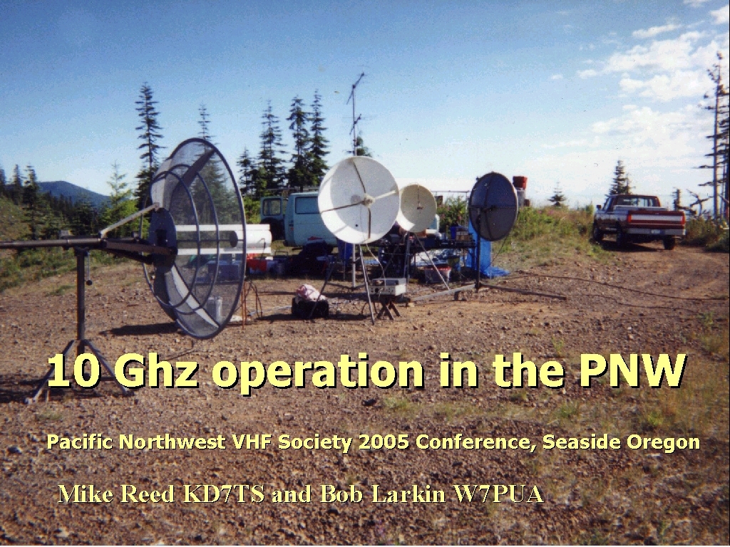
Part 1. Portable from High or Clear Locations
This can be a lot of fun. We pick locations that are virtually guaranteed to be successful due to line of sight paths, and the results are immediate. It has been compared with shooting fish in a barrel. In spite of the apparent ease of making contact, there have been failures of two stations to get hooked up. This is pretty basic stuff, but I want to show a little background of why aiming is so critical to successful operation.
Let's start by looking at two stations equipped with 10 mw and 17 db horns.
- Distance between Unit 39 and Unit 40 is 90.6 km (56.3 miles)
- Propagation mode is line-of-sight, minimum clearance 29.3F1 at 60.0km
- Average frequency is 10368.100 MHz
- Free Space = 151.9 dB, Obstruction = 1.7 dB
- Urban = 0.0 dB, Forest = 0.0 dB, Statistics = 15.9 dB
- Total propagation loss is 169.5 dB
- System gain from Unit 39 to Unit 40 is 191.0 dB
- System gain from Unit 40 to Unit 39 is 191.0 dB
- Worst reception is 21.5 dB over the required signal to meet 90.0% of time, 90.0% of locations, and 90.0% of situations
Statistics is a term that allows for variations in changing path parameters. We will allow that the operator will wait long enough to eliminate QSB, and be able to copy CW to a ZERO db S/N.
So, what this report says is that the path will have 153 db of loss. No matter what happens at the transmitter, it will be 153 db lower in front of the distant end, and may go 16 db lower during fades.
To overcome this path, we need to have system gain which will come from both the transmitter end and the receiver end.
The transmitter has 10 MW, which is +10 dbm, and we get to add the transmit antenna gain to this, for a total transmit signal of +27dbm. Now our signal must go 90.64 miles, through a 153 db attenuator, and arrives in front of the receive antenna as a -126 dbm signal. Now we add the receive antenna gain of 17 db and we have -109 dbm going to the antenna port of our system.
Assuming a receive system NF of 2 db and a bandwidth of 500 Hz, we can go to a -145 dbm. This does not include the receive antenna. This simply means if we hook the system antenna port to a signal of - 145 dbm, we might be able to copy it.
All the numbers are here , so what do they tell us?
Total system gain is:
10 dbm + 17 db +17 db + 145 dbm = 189 db (gain)
Path loss = 153
----------------
36 db
This means an experimenter with a decent CW ear will always have a signal at least 20 db out of the noise, and some of the time it might be as high as 36 db above the noise. This assumes the antennas are perfectly aimed at one another. What happens if they are not ? Our 17 db horn has a half power beamwidth of 10 degrees. This means 5 degrees either side of bore sight the E field and H field will be 3 db less. This still leaves a 33 db margin, or does it? Some of the time it might be 16 db lower due to fading, so maybe through poor timing we will only have a margin of 17 db.
We can continue this analysis incrementally, but let's just skip to both stations being somewhat off bore sight by a number we choose. Let's choose 9 degrees for both ends. It does't matter which plane is misaligned, elevation or azimuth, the effect and magnitude are nearly the same.
By inspection of a pattern chart we see that the pattern is about 8 db down at 9 degrees either side of ZERO. Subtracting 8 db from each antenna at both ends of this path we no longer have 189 db of system gain. It is now 173 db of system gain.
Total system gain is:
10 dbm + 9 db +9 db + 145 dbm = 173 db (gain)
Path loss = 153
----------------
20 db
This looks pretty good, until we remember that this is our peak signal, and can sometimes be 16 db lower. 4db out of the noise is still pretty good, and it is likely that the antennas would get peaked after hearing a weak signal coming through.
But, suppose you are not on frequency, can you find a signal that is 4 db out of the noise by tuning around ? What if the other station is aimed off by 15 degrees ? There may be nothing to tune for.
Let's try another example with the same antennas, but one end has invested in a 2 W amp.
- Distance between Unit 39 and 2W17db is 90.6 km (56.3 miles)
- True North Azimuth = 67.3°, Elevation angle = -0.6149°
- Terrain elevation variation is 1143.7 m
- Propagation mode is line-of-sight, minimum clearance 29.3F1 at 60.0km
- Average frequency is 10368.100 MHz
- Free Space = 151.9 dB, Obstruction = 1.7 dB
- Urban = 0.0 dB, Forest = 0.0 dB, Statistics = 15.9 dB
- Total propagation loss is 169.5 dB
- System gain from Unit 39 to 2W17db is 190.5 dB
- System gain from 2W17db to Unit 39 is 213.5 dB
Worst reception is 21.0 dB over the required signal to meet 90.0% of time, 90.0% of locations, and 90.0% of situations.
Nothing seems to have changed.
Total system gain is:
10 dbm + 17 db +17 db + 145 dbm = 189 db (gain)
Path loss = 153
----------------
36 db
The wrong station is transmitting to take advantage of the amplifier, we need to swap roles.
33 dbm + 17 db +17 db + 145 dbm = 212 db (gain)
Path loss = 153
----------------
59 db
Some of the time it might be 16 db lower due to fading, so maybe through poor timing we will only have a margin of 43 db. ( around 10 - 20 db over S9)
Allowing 16 db for poor antenna alignment, the signal is still around S9, even during fades, at the receive end. This should allow plenty of margin for tuning around. Once the frequency is nailed, then antennas are easily peaked.
Keep in mind, this is on a line of sight path with stations that are fairly well aligned initially. The two Watt amp doesn't change the margin when the 10 MW end is doing the transmitting. It is always better to have the 10 MW end look for the 2 W station.
We'll' take a quick look at 1 W stations and 2 foot dishes, just for a quick comparison.
- Distance between Unit 41 and Unit 42 is 90.6 km (56.3 miles)
- True North Azimuth = 67.3°, Elevation angle = -0.6149°
- Terrain elevation variation is 1143.7 m
- Propagation mode is line-of-sight, minimum clearance 29.3F1 at 60.0km
- Average frequency is 10368.100 MHz
- Free Space = 151.9 dB, Obstruction = 1.7 dB
- Urban = 0.0 dB, Forest = 0.0 dB, Statistics = 17.1 dB
- Total propagation loss is 170.8 dB
- System gain from Unit 41 to Unit 42 is 242.0 dB
- System gain from Unit 42 to Unit 41 is 242.0 dB
Worst reception is 71.2 dB over the required signal to meet 90.0% of time, 90.0% of locations, and 90.0% of situations
Being on 10368.1 precisely can be a good thing, but what is required is that both stations be on the same frequency and stay there.
If two stations can work on 432.01 or 1296.02 then each should be able to tune the 24th or 8th harmonic to get on 10368.24 or 10368.16. This puts both stations on the same frequency at 10 GHz.
If frequency issues cannot be resolved, then you must tune over the expected range and hope to find the other stations frequency. Recent experience in the 10 GHz cumulative contest and the September VHF contest shows that a stable 10 MHz reference oscillator can be used to stabilize a 10 GHz transverter through a PLL generated 106.5 MHz to "injection" lock the transverter. It can very useful to establish some method of "talk-back". Two meters is common, but other bands can be just as useful. Pick a frequency that is clear, and likely to stay clear. It is frustrating to find someone already on your talk-back frequency running the 50 stations that haven't worked him yet!
Whether or not you can be on the same frequency, AIMING the antenna is crucial. Our target should be, to aim better than, or at least equal to, half the 3 db beamwidth. For the 17 db horn, on 10 GHz, this about 5 degrees. In the case of a 2 foot dish on 10 GHz, we need to shoot for 1 3/4 degrees. This is easily done if you know where the other station is located. Azimuth and elevation are equally important. Generally elevation can be set to ZERO.
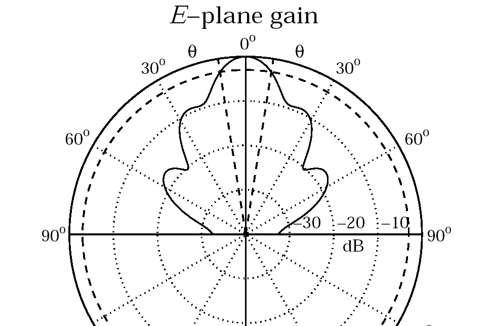
E-Plane pattern of 17 db antenna
If there is enough sun to cast shadows you can peak on sun noise, then use a preprinted list of sun azimuth to calibrate your antenna heading. If you have a setting circle, and set it now, then you can are calibrated to True headings for the duration of your stay at this location.. If conditions or circumstances don't favor the Sun solution, then a compass will be the tool to help you point your antenna.
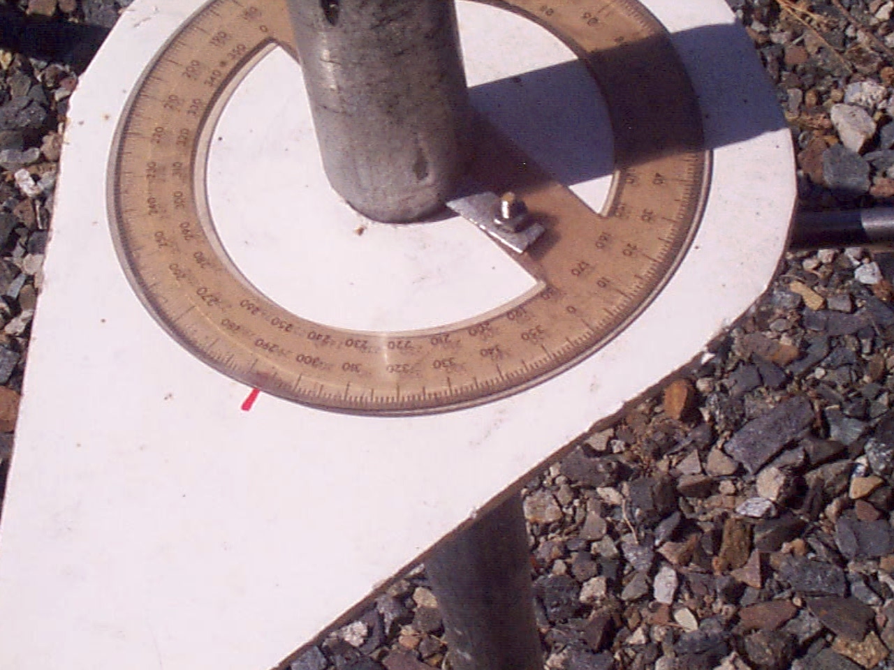
Again, the setting circle can make life easier for subsequent efforts on different headings and the setting circle can be set to either true or magnetic headings. For the compass to be useful, it must allow bearings to be read while sighting over the compass.
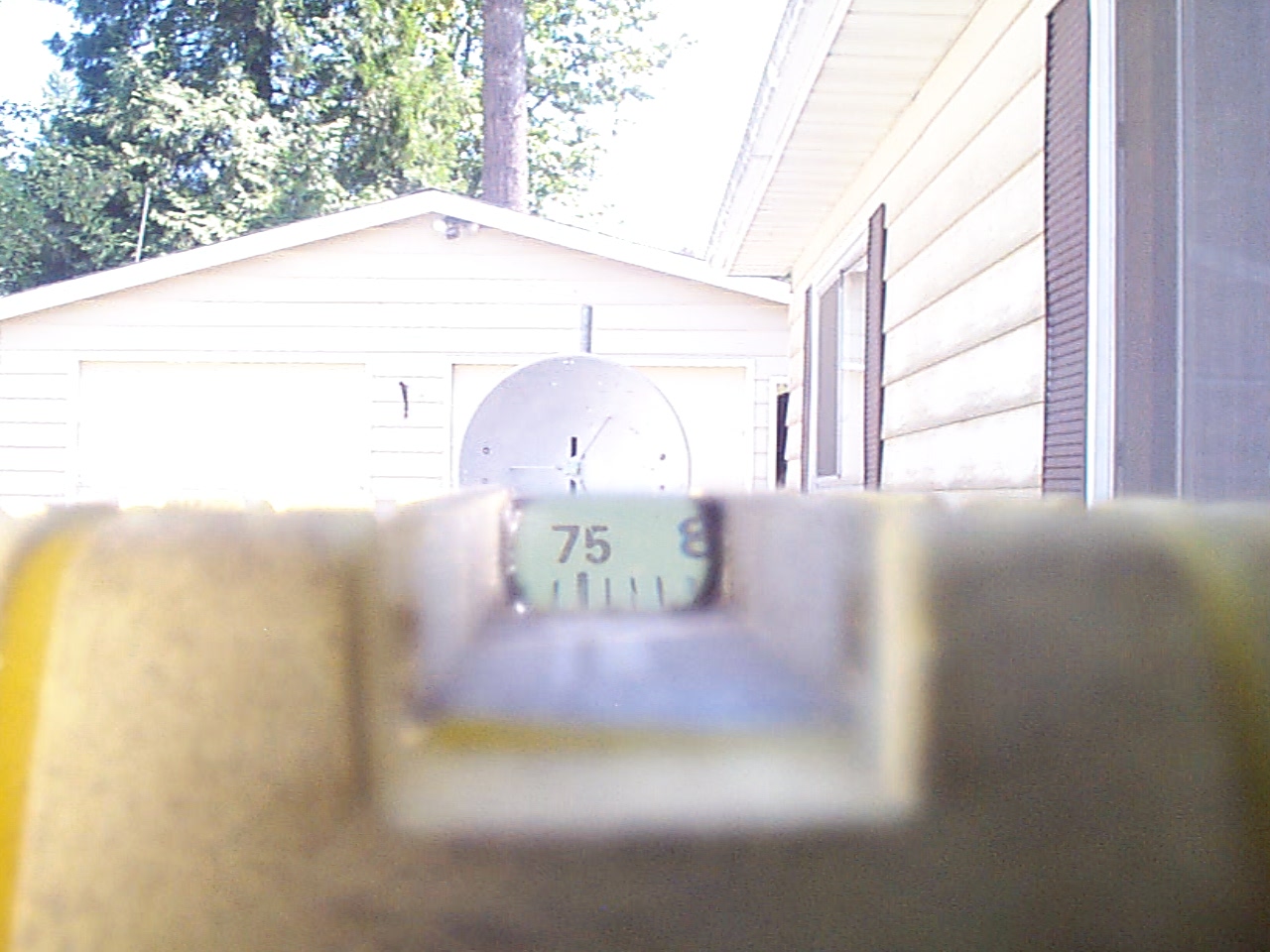
This is the view through the handbearing compass aligned with the dish feed and an index mark on the reflector. There are marks above the numbers as well as below, but difficult to capture with the camera. You can read this compass to a 1/2 degree. A little time spent getting the dish properly aimed pays huge dividends in operating time.
Keep in mind the view is 180 degrees opposite, since we are looking into the dish. Sighting can also be done across the edges of the dish with 90 degrees applied to the reading as needed. This is useful when the antenna is set at the edge of a precipice, and there is no view into the face.
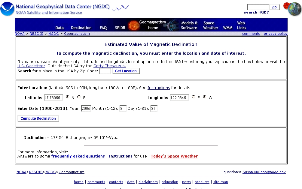
There is some additional information needed to use a compass reading. Locations and headings should be gathered before you leave home. Here is one resource on the WWW for the home computer that make this easier:
This website will give you the declination (difference between Magnetic and True) for the operating location on the day you intend to operate. Probably greater accuracy than required, but need only be checked every few years.
bd_2000.exe is a great little DOS program to show headings and distance between locations.
WINGRID by W4SM is another handy distance and bearing tool, but written for the MS Windows environment.
Radio Mobile is a great program for doing headings, distance and path loss. It is not simple to set up, and not required to find the answers. It is very good. With the SRTM1 and SRTM3 data sets it is better than most topo programs for radio work. It does not show roads and rivers or geographic boundaries, unless you import them while on-line.
There are Topo programs, like Topo USA that will work very nicely to show "line of sight" paths. Generally, for the majority of our work, the radio horizon doesn't vary enough from LOS to worry about.
Part 2. Home Operation
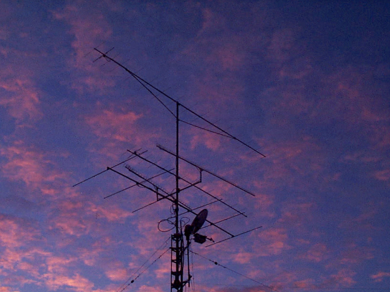
Ernie, W7LHL, 10 foot dish with 4 Watt amp and preamp mounted at the feed. System NF 1 db or less.
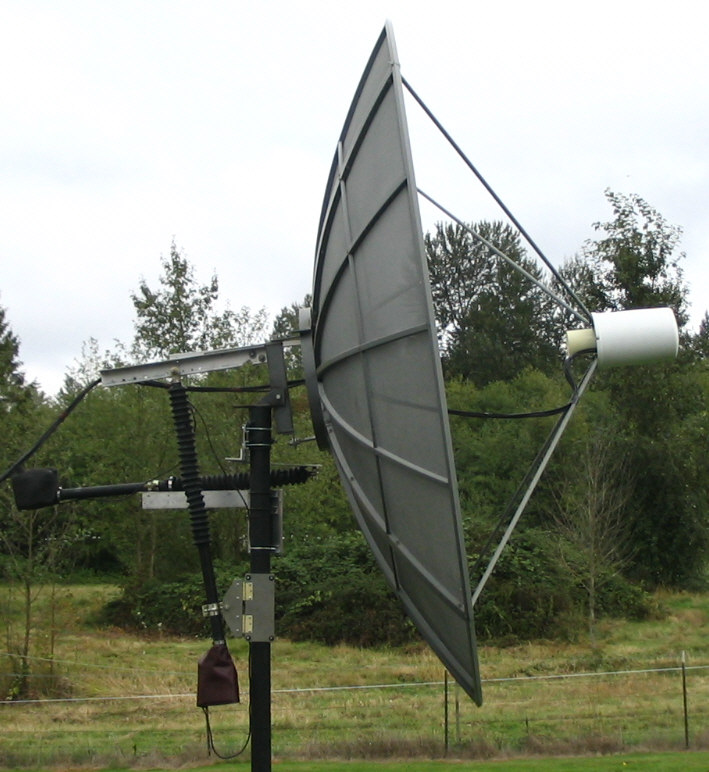
Offset dish at KD7TS has all equipment mounted in a weather tight box suspended from the feed arm. Power is 1 watt and system NF about 2 1/2 db.
In the previous example of portable operation, the location was chosen because it provided a line of sight path. Most of the paths available to home stations are not line of sight and fall into the category of Troposcatter. We will examine a path that has actually been used between 2 home stations.
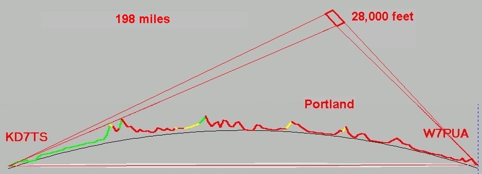
This path is described in "Radio Mobile" as "scatter, double horizon" , and is a Troposcatter path. As shown in the picture, the common volume is over the west side of Portland, Ore centered around 28,000 feet. Terrain elevations and altitude are exaggerated, and the common volume is also not as large as it might appear in the picture. The takeoff angle at Bob's end is terrain limited to four degrees elevation, and Mikes end is peaked when elevation is a half to one degree up. On an average day the signal is predicted to be 33 db below the detection threshold at Bobs, and 21 db too low at Mikes.
Aiming and frequency are the same problems identified earlier for the line of sight path.
Aiming of both antennas is critical, but easily accomplished from the home. KD7TS uses sun noise and the DSP-10 to confirm calibration of the antenna, and W7PUA aims with the aid of the handbearing compass pictured in the previous section. It should be obvious that under normal conditions antennas cannot be peaked by audible signals.
We are both using a 10 Mhz reference oscillator, disciplined by a GPS controller, to control the frequency of the transverter and the DSP-10.
Time might be the single most important ingredient for our operations. The portable operator is limited in how much time he is willing to spend making a contact. This does not need to be the case for the home based microwave experimenter.
- Distance between KD7TS and W7PUA is 318.3 km (197.8 miles)
- True North Azimuth = 194.5°, Magnetic North Azimuth = 176.8°, Elevation angle = -1.4259°
- Terrain elevation variation is 828.1 m
- Propagation mode is scatter, double horizon, 44.1F1 at 77.0km
- Average frequency is 10368.100 MHz
- Free Space = 162.8 dB, Obstruction = 105.8 dB, Urban = 0.0 dB, Forest = 0.0 dB, Statistics = 16.1 dB
- Total propagation loss is 284.6 dB
- System gain from KD7TS to W7PUA is 251.6 dB
- System gain from W7PUA to KD7TS is 257.6 dB
- Worst reception is 33.0 dB below the required signal to meet 90.0% of time, 90.0% of locations, and 90.0% of situations
An interesting example of home station operation is a contact completed on May 18, 2004. Using the "beacon operation" feature of the DSP-10, Bob and I had been transmitting back and forth every 5 minutes for weeks. We both noticed that signals were getting strong, so beacon operation was changed to CW and we completed a contact very easily. During the contact signals continued to improve, so I called Bob on USB and we exchanged again in that mode. The enhancement did not last very long, but by being on the air we were able to see when it happened and take advantage of the brief enhancement.
This type of operation is possible with stable frequency control, accurate antenna aiming and great deal time. Other contacts have been completed in PUA43 mode using the DSP-10 and time to provide the needed signal enhancement. This can, and has been done in the field, but is much easier between home stations where you can spend as much time as needed to get the information exchanged.
I did a quick and dirty page of my first "DX" QSO with W7SZ on 10368 at:
Bob, W7PUA distilled a great deal of data into an interesting presentation that is online at:
Beb, W7SLB has more details of other home station contacts at: